

Appearance
Capacitance identification
While the resistance parameters determine the magnitude of the voltage losses, the capacitance parameters determine how quickly the polarization voltages change with time. Together, the resistance and capacitance of each RC branch define the dynamic behaviour of the battery.
The capacitance values are obtained from the polarization resistances and the relaxation time constants identified during curve fitting.
The capacitance parameters identified are:
- First polarization capacitance (
) - Second polarization capacitance (
)
The relationship between the resistance, capacitance, and time constant of an RC branch is given by
where:
is the time constant, is the polarization resistance, is the polarization capacitance.
Rearranging the equation gives
This relationship is used to determine the capacitance values of each polarization branch.
First polarization capacitance (
The first polarization capacitance is associated with the fast transient response represented by the first RC branch.
Once the first polarization resistance and time constant have been identified, the capacitance is calculated as
where:
is the first relaxation time constant, is the first polarization resistance.
The value of
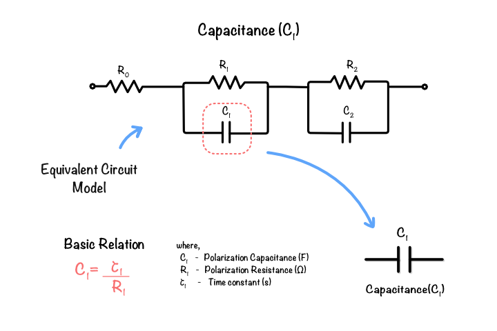 Figure 6.4 : First RC branch illustrating
Second polarization capacitance (
The second polarization capacitance is associated with the slower transient response represented by the second RC branch.
It is calculated using
where:
is the second relaxation time constant, is the second polarization resistance.
The value of
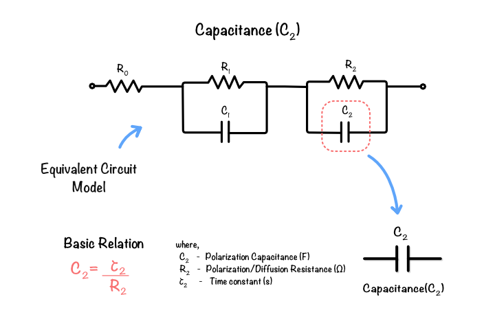 Figure 6.5: Second RC branch illustrating
Together, the resistance and capacitance parameters define the dynamic characteristics of the second-order Thevenin Battery Model. However, these parameters cannot be obtained directly from the measured voltage response. Instead, they are identified by fitting a mathematical model to the relaxation curve, as described in the next section.