

Appearance
Resistance identification
The resistance parameters of the second-order Thevenin Battery Model describe the voltage losses that occur when current flows through the battery. These parameters are identified by analysing the voltage response measured during the Hybrid Pulse Power Characterization (HPPC) test.
When a current pulse is applied to the battery, the terminal voltage exhibits two distinct behaviours. The voltage first undergoes an instantaneous drop caused by the battery's internal resistance, followed by a gradual change resulting from electrochemical polarization. These voltage characteristics are used to determine the resistance parameters of the Thevenin model.
The resistance parameters identified are:
- Ohmic resistance (
) - First polarization resistance (
) - Second polarization resistance (
)
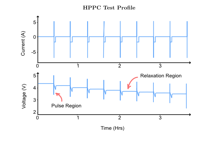 Figure: HPPC voltage response highlighting the instantaneous voltage drop and relaxation regions.)
Ohmic resistance (
The ohmic resistance represents the immediate voltage loss that occurs when current begins to flow through the battery. It accounts for the resistance of the electrodes, electrolyte, current collectors, and electrical connections.
Because this voltage change occurs almost instantaneously, the ohmic resistance can be determined directly from the voltage step at the beginning of a current pulse.
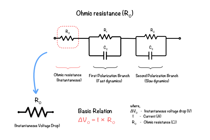 Figure 6.1: Determination of
The ohmic resistance is calculated as
where:
is the instantaneous voltage change, is the applied current step.
The value of
First polarization resistance (
Following the instantaneous voltage drop, the battery voltage continues to change due to electrochemical polarization. The first polarization resistance represents the fast polarization process modelled by the first RC branch.
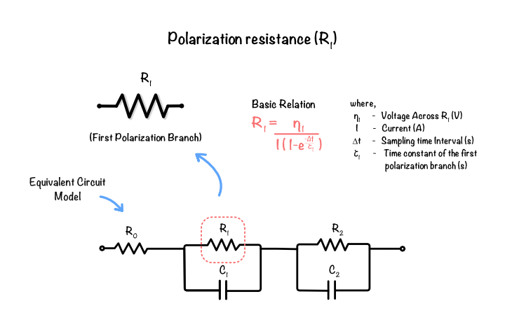 Figure 6.2: Determination of
After fitting the voltage relaxation curve, the first polarization resistance is determined using
where:
is the voltage associated with the first RC branch, is the applied pulse current, is the pulse duration, is the first relaxation time constant.
This parameter determines the magnitude of the fast transient voltage response.
Second polarization resistance (
The second polarization resistance represents the slower electrochemical processes that continue to influence the terminal voltage after the fast transient has decayed.
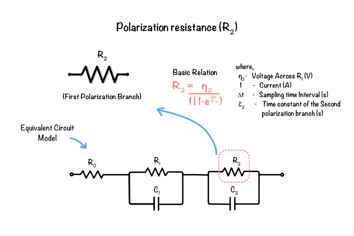 Figure 6.2: Determination of
where:
is the voltage associated with the second RC branch, is the applied pulse current, is the pulse duration, is the second relaxation time constant.
The value of
Together, the three resistance parameters describe both the instantaneous and time-dependent voltage losses of the battery.
The next section explains how the capacitance values associated with the polarization branches are determined.